Gas Discharge Flow Calculator for Choked and Subsonic Gas Flow Conditions

Calculate Gas Flow Through Valves and Pipes Under Pressure Differential

online since 2012
Choose Your Preferred Way to Calculate

Online Calculator

This calculator is not available as Online app.

Desktop App

Pressure drop calculator

Desktop full-featured version.

Free Trial Available
⬇️ Download for Windows ⬇️ MacOS / Linux

Gas Outflow Calculator – Adiabatic Flow of Perfect Gases

Adiabatic gas flow describes a flow process in which no heat transfer occurs between the flowing gas and the surrounding environment.

In practical engineering applications, adiabatic conditions can be assumed for short flow sections, such as short pipelines, valves, fittings, and discharge openings, where heat exchange effects are negligible.

This gas outflow calculator is used to analyze the discharge of compressible gases from pipelines or pressurized vessels through a small opening into the atmosphere or into another pipeline or tank. Under these conditions, gas flow can be treated as both adiabatic and compressible, which is essential for accurate flow rate and velocity calculations.

Subsonic, Sonic And Supersonic Gas Flow

A characteristic of this type of flow is a very high discharge velocity due to a significant pressure difference. When the flow velocity reaches the speed of sound under local gas temperature and pressure conditions, the amount of gas that can discharge becomes limited. Such flow is referred to as choked flow, and the maximum flow rate is achieved.

The maximum flow rate can be calculated using the following formula:

w = 1.111× 10 -6 Yd 2 Δpρ K

Where:

  • w - mass flow rate kg/s
  • Y - expansion coefficient
  • d - internal diameter of the discharge opening m
  • Δp - pressure difference upstream and downstream of the discharge opening Pa
  • ρ - gas density kg/m³
  • K - local flow resistance coefficient

To achieve a discharge velocity higher than the maximum under the conditions described above, the discharge must occur through a specially shaped nozzle consisting of a convergent and a divergent section. In the central section of such a nozzle, the gas flow velocity must reach the speed of sound for the given pressure and temperature conditions.

The speed of sound can be calculated using the following formula:

c = κ RT

Where:

  • c - speed of sound m/s
  • κ - isentropic coefficient
  • R - gas constant J/kgK
  • T - gas temperature K

Under such conditions, the gas flow velocity downstream of the throat continues to increase in the divergent section to values exceeding the speed of sound. When analyzing gas flow where the flow velocity approaches or exceeds the speed of sound, the Mach number is used, which can be calculated as follows:

M = v c

Where:

  • M - Mach number
  • v - gas flow velocity
  • c - speed of sound

If the Mach number is less than 1, the flow is subsonic; if it equals 1, the flow is sonic; and if it is greater than 1, the flow is supersonic. The Mach number is most commonly used in aviation to describe aircraft speed, while in pipeline fluid flow, supersonic flow is uncommon. The most typical case for high gas velocities in pipelines is the achievement of maximum flow, for example in control and safety valves for natural gas, liquefied petroleum gas, steam, cryogenic gases, and similar technical gases.

Choked flow occurs during gas discharge when the pressure difference exceeds the value required for the flow velocity to reach the speed of sound. This critical pressure ratio can be calculated for known gas pressure and temperature parameters when discharging into free atmosphere and is approximately 0.528 for diatomic gases such as air. In other words, if the absolute gas pressure in the pipeline is approximately twice the absolute atmospheric pressure, the conditions for maximum flow – choked flow – are achieved.

A characteristic of this type of flow is that a reduction of gas pressure in the discharge area does not increase the discharge flow rate, while an increase in upstream pipeline pressure can increase the discharge flow rate, since the increased pressure also increases the speed of sound, enabling a higher discharge velocity.

The pressure ratio that leads to maximum flow – choked flow – can be calculated as follows:

p2 p1 = 2 κ + 1 κ κ - 1

Where:

  • p1 - gas pressure upstream of the discharge location
  • p2 - gas pressure downstream of the discharge location at which critical flow with maximum flow rate occurs
  • κ - isentropic coefficient

This pressure ratio is called the critical ratio and for air, where κ = 1.4, it equals 0.528. The resulting temperature ratio under choked flow conditions can be calculated as follows:

T2 T1 = 2 κ + 1

Where:

  • T1 - gas temperature upstream of the discharge location
  • T2 - gas temperature downstream of the discharge location at which critical flow occurs
  • κ - isentropic coefficient

In practice, it is common for the external surface of a valve to freeze during such flow conditions, as the gas temperature achieved during choked flow can drop below 0 °C, causing moisture from the surrounding air to freeze on the valve surface.

After the gas exits a high-pressure pipeline, if choked flow is achieved at the narrowest cross-section, the gas velocity in the atmosphere continues to increase until the pressure of the discharging gas equalizes with the ambient pressure.

Registration

Select a fair price and enable the full service:

  • Switch between metric and imperial units in one click
  • Export calculation results in Word .docx or Excel .xlsx format
  • Preview results on one place and copy/paste it in your favorite text editor
  • Send results back to your email
  • Support the future of this project

And even more... get access to the full set of 19 desktop calculators available for MacOS, Linux or Windows.

Full Year Service

Prepaid Monthly Cost
$2.50/month

Full year $29.95/year

When is this calculator suitable?

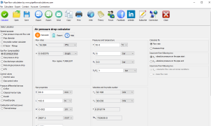
The Gas discharge flow calculator is a specialized tool designed to compute the flow rate of gases exiting pipelines or reservoirs, considering factors such as pressure differences, pipe diameters, and the presence of valves and fittings.

It supports calculations for various two- and three-atomic gases, including air, nitrogen, and carbon dioxide, under steady flow conditions with constant pressures.

The calculator employs the Darcy formula, modified for gas flow, and utilizes the Colebrook-White equation to determine friction factors. It also assesses whether the flow is choked and provides relevant calculations for such scenarios. Users can input parameters like resistance coefficients for valves and fittings, as well as pipeline surface roughness, to obtain accurate results.

You can use the calculator for flow in pipelines that include valves and fittings. You can calculate the maximum flow rate when you know pressure difference and pipe diameter, or you can calculate pipe diameter when you know flow rate and pressure drop.

The calculator is applicable for all two and three atomic gases, like air, nitrogen, carbon dioxide and other gases. The calculator is suitable for steady flow with constant pressures at one point of streamline.

What are the calculator restrictions?

The calculator is suitable for ideal gases, as the calculator uses the equation of state for ideal gas during calculation. The calculator is not applicable for non-steady, pulsating flow.

How is the calculation executed?

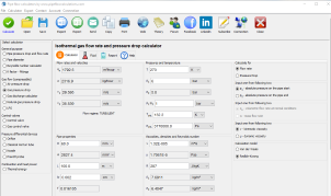
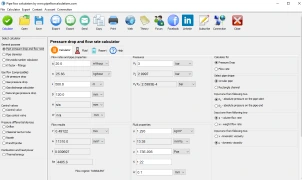
Based on the known pressure difference (head loss) between one point of flow stream at the start of a pipe or in front of a valve, to the outside point (like atmosphere), or after a valve with known inside pipe diameter, mass flow rate, and volume discharge flow rate is calculated. The calculator uses a modified Darcy formula for flow rate calculation.

w = 1.111× 10 -6 Yd 2 Δpρ K

where is:

w - offtake mass flow rate [kg/s]
Y - expansion factor [ - ]
d - internal pipe diameter [mm]
Δp - pressure drop [Pa]
ρ - density [kg/m3]
K - resistance coefficient [ - ]

The calculator is calculating a friction coefficient using the Colebrook-White formula:

1f = -2.0 log ( kr 3.7065D + 2.5226 Ref )

where is:

f - friction factor [ - ]
k - pipe roughness [mm]
D - internal pipe diameter [mm]
Re - Reynolds number [ - ]

The gas discharge calculator presents Reynolds number and expansion factor as calculation results.

The calculator is checking if a flow is choked or not and presents choked flow status. For choked flow conditions, the calculator is calculating the flow rate for that condition.

What else has to be known to perform the gas discharge calculation?

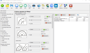
You should enter resistance factor K for valves and fittings if they exist in the pipeline as well as pipeline surface roughness.

When is this calculator not relevant?

The calculator is not relevant for liquids.

Desktop App

Pressure drop calculator
Professional-grade pipe flow calculations
Fast. Accurate. Reliable.
Free Trial Available
Win Download MacOS / Linux

Features in desktop app

  • Save/Open multiple results
  • Export to Word and Excel
  • Print results
  • Create list of custom fluid properties
  • Resistance factor K for valves/fittings
  • Pipe surface roughness selection
  • Pipe material selection
  • Gauge vs absolute pressure toggle
  • Compressible isothermal flow
  • Dry air isothermal flow
  • Gas offtake flow
  • Natural gas flow
  • No admin rights required to install

Need a helping hand?

Powered by natural intelligence - NI

calculation_guru

If you need a quick calculation, but you are not still familiar how to use the calculator, you can order calculation service from the calculator developer.

📋 Order calculation service