Orifice Plate Calculator for Flow Rate and Sizing Calculation
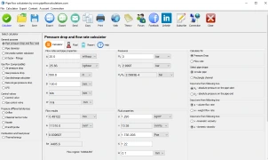
This orifice plate calculator is used to perform flow rate and orifice sizing calculations based on the measured pressure drop. The calculation follows standard orifice flow equations commonly used in flow measurement and fluid mechanics. Use the calculator below for accurate orifice plate and flow calculation in piping systems.
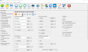
Orifice plate sizing and flow rate calculation
Flow Rate Calculation for Fluids Through an Orifice or Nozzle
The flow rate of a fluid passing through an orifice or nozzle can be determined using the following equation:
Fluid Flow Through an Orifice or Nozzle
Where:
- q = Flow rate
- Cd = Coefficient of discharge
- A = Cross-sectional area
- β = Diameter ratio (d₁/d₂)
- gₙ = Acceleration due to gravity
- hL = Head loss
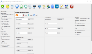
Instead of using the coefficient of discharge (Cd), a more practical approach is to apply the flow coefficient (C), which is defined as:
Flow Coefficient Formula
Where:
- C = Flow coefficient
- Cd = Coefficient of discharge
- β = Diameter ratio (d₁/d₂)
By utilizing the flow coefficient, engineers and fluid mechanics professionals can achieve more accurate calculations for fluid dynamics, hydraulic systems, and nozzle flow efficiency.
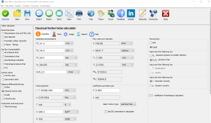
Coefficient of Discharge for Orifice Flow (ISO 5167)
The coefficient of discharge (Cd) for orifice flow can be determined using the Reader-Harris/Gallagher (1998) equation as specified in ISO 5167:
Coefficient of Discharge Formula

Where:
- β = Diameter ratio (d₁/d₂)
- ReD = Reynolds number based on the larger diameter
- d₁ = Smaller internal diameter
- d₂ = Larger internal diameter
Tap Configurations and Coefficient Adjustments
The values of L₁ and L₂ depend on the type of pressure tap used:
- Corner taps: L₁ = L₂ = 0
- D and D/2 taps: L₁ = 1, L₂ = 0.47
- 1-inch taps: L₁ = L₂ = 0.0254/d₁ (for d₁ in meters)
By applying these fluid flow equations, engineers can enhance flow measurement accuracy in hydraulic systems, pipelines, and industrial fluid applications.
2D DWG / PDF drawing request
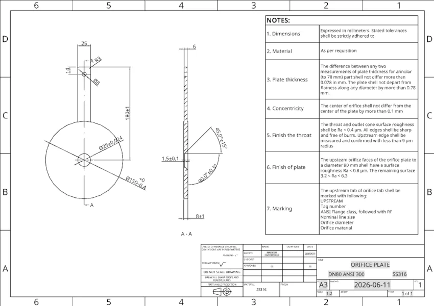
Need a 2D drawing?
Automatic STEP model generation is available directly from this calculator. 2D drawings in PDF format are currently prepared on request.
Send me your calculated dimensions and I can prepare a 2D drawing as DWG / PDF file for your orifice plate.
The automatic DWG / PDF generator is planned, but for now this option is handled as DWG / PDF file, manually.
Download This Calculator
This calculator is available as desktop application for Windows and macOS.
Free trial is available for new users.
Registration
Select a fair price and enable the full service:
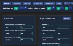
- Switch between metric and imperial units in one click
- Export calculation results in Word .docx or Excel .xlsx format
- Preview results on one place and copy/paste it in your favorite text editor
- Send results back to your email
- Support the future of this project
And even more... get access to the full set of 19 desktop calculators available for Windows / macOS.
Full Year Service
Prepaid Monthly Cost
$3.33/month
Full year $39.95/year