Resistance Coefficient K and Equivalent Length Calculator
calculate K values and minor loss coefficients for valves and fittings – desktop application
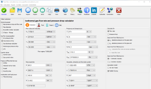
Online Calculator
This calculator is not available as Online app.
Registration
Select a fair price and enable the full service:
- Switch between metric and imperial units in one click
- Export calculation results in Word .docx or Excel .xlsx format
- Preview results on one place and copy/paste it in your favorite text editor
- Send results back to your email
- Support the future of this project
And even more... get access to the full set of 19 desktop calculators available for Windows / macOS.
Full Year Service
Prepaid Monthly Cost
$3.33/month
Full year $39.95/year
Minor Loss Coefficients and K Values for Pipe Fittings
Pressure loss in piping systems consists of:
- Major losses, caused by friction along straight pipe sections
- Minor losses, caused by fittings, valves, bends, contractions, and expansions
Minor losses are quantified using resistance coefficients (K values) obtained from experimental data and standardized tables.
The calculator includes K values for:
- 90° elbows, return bends, and mitre bends
- Standard elbows and tees
- Pipe entrances and exits
- Sudden and gradual enlargements and contractions
- Valves (gate, globe, ball, butterfly, check valves, etc.)
Each fitting introduces additional energy dissipation that must be accounted for in system design.
Head Loss Equations Used in Pipe Flow Analysis
The total head loss in a piping system is the sum of major and minor losses.
Major Head Loss (Darcy–Weisbach Equation)
Where:
- hf = major head loss
- f = Darcy friction factor
- L = pipe length
- D = pipe diameter
- V = flow velocity
- g = gravitational acceleration
Minor Head Loss Equation
Where:
- hm = Minor head loss
- K = Minor loss coefficient
- V = Flow velocity
- g = Acceleration due to gravity
Minor losses become significant in systems with many fittings or short pipe runs.
Sudden Enlargement and Contraction
Using the momentum, continuity, and Bernoulli equations, the resistance coefficient for sudden enlargement and sudden contraction can be expressed as a function of pipe diameters:
Sudden enlargement:
Sudden contraction:
- K1 = resistance coefficient
- d1 = smaller internal diameter
- d2 = larger internal diameter
Using the diameter ratio:
the resistance coefficient can be written in simplified form.
Sudden enlargement:
Sudden contraction:
To express the resistance coefficient based on the larger pipe diameter, the following relation applies:
- K1 = resistance coefficient based on smaller diameter
- K2 = resistance coefficient based on larger diameter
Sudden Enlargement and Contraction
If the enlargement or contraction is gradual, the resistance depends on the angle of divergence or convergence.
For gradual enlargement, the Gibson coefficient (Cₑ) is used to account for different divergence angles.
If the angle of divergence exceeds 45°, the resistance coefficient approaches that of a sudden enlargement.
For gradual contraction, the contraction coefficient (C𝑐) based on Crane test data is applied for various convergence angles.
Using these coefficients, the resistance coefficient can be calculated as:
- Gradual enlargement:
- Gradual contraction:
The resistance coefficient can be expressed relative to either the smaller or larger pipe diameter, depending on the calculation basis.
Application to Reduced-Bore Valves
The equations for gradual enlargement and contraction can also be applied to reduced-bore straight-through valves, such as:
- Ball valves
- Gate valves
For these valves, the total resistance coefficient is calculated as the sum of the contraction and enlargement resistance coefficients.
FINAL NOTE
You can use this calculator to determine:
- Resistance coefficient K
- Equivalent length l/d
- Minor head losses for fittings and valves
These results can be directly used in conjunction with a pressure drop calculator to evaluate piping system efficiency and ensure accurate hydraulic design.
Register account and unlock full access
Desktop App

Fast. Accurate. Reliable.
Features in desktop app
- Save/Open multiple results
- Export to Word and Excel
- Print results
- Create list of custom fluid properties
- Resistance factor K for valves/fittings
- Pipe surface roughness selection
- Pipe material selection
- Gauge vs absolute pressure toggle
- Compressible isothermal flow
- Dry air isothermal flow
- Gas offtake flow
- Natural gas flow
- No admin rights required to install
Need a helping hand?
Powered by natural intelligence - NI

If you need a quick calculation, but you are not still familiar how to use the calculator, you can order calculation service from the calculator developer.