Short instructions for calculator use
- Calculate the actual flow and required head of the pump (or ventilator) for known pump performance curves and known piping characteristics (diameter, length, local resistance, surface roughness)
- Calculate the actual flow and head of the pump for the variable pump speed
- Calculate pump flow for different pipeline lengths, different pipeline diameters, etc
- Quickly and easily notice how different the thickness of the pipe wall affects the fluid flow, for the same nominal outside pipe diameter
- The calculator shows visually how much of the pump's head is used to overcome the useful -
static pressure and how much energy losses are due to friction in the pipeline or due to
local resistance, so you can reduce the pump speed and get the same flow without energy loses.
- An equation that approximates the performance curve of pump is presented
- Graphic representation of the pump performance curve, pipeline and operating (intersection) points
- Usable for incompressible fluid flow - liquids and gases as well, at low pressure drops
Features list
- Selection of fluid from the available list
- Selection of standard pipe from the available list
- Applicable for round and rectangular pipelines and ducts
- Selection of units of measurement in the metric and imperial system
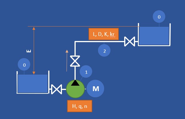
Pump - pipeline - reservoir example
Pump characteristics
Intro
Each pump has its own unique characteristic - a curved line that shows relation of the actual head to a certain flow at constant speed.
Such a curve is the characteristic of the pump.
When this page loads, several values of head and flow have already been entered in the pump characteristics table,
and these are a characteristic of the well-known Grundfoss size 45 CP pump.
Units of measure
Before entering the pump characteristic value, you can select the units of measure for head H and flow q.
Pump performance
The calculator allows you to enter several combinations of head and flow rates in the table for the selected characteristic.
At least three combinations head-flow need to be entered. The maximum number is not limited, but there is no need to enter more than five head-flow combinations.
Editing and deleting
By using the edit option, you can change existing values to suit your specific pump.
You can also delete unnecessary operating points, but the calculator does not allow the number of entered head - flow combinations to be less than three.
Pump speed
The calculator expects you to enter the value of the pump speed (rpm) - n₁ at which the entered head - flow combinations apply.
In the next text field - n₂, the calculator allows you to enter another desired pump speed (rpm).
This is a very useful feature if the pump have the ability to change the speed using a frequency converter, VFD or EC motor.
Pump performance curve approximation
After entering all the quantities, an approximate function is displayed at the bottom, which shows the dependence of the pump head and flow, at variable speed n₂. That curve is visible at the pump performance diagram.
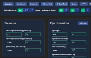
Pipe line characteristics
Pipe shape and size
The calculator allows you to use it for round pipes and rectangular channels. Before entering data for the pipeline, it is necessary to first choose one of these two types - round pipe or rectangular channel.
For round pipes, you can choose one of the standard pipes offered. There are several standards available, and it is necessary to choose the nominal diameter and schedule. The calculator calculates the inner diameter and enters the value in the field - internal diameter D.
If the pipe standard is not known, you can enter free values for the inside diameter D, or the width W and the height H of the channel.
Other pipeline properties
For the calculation, it is necessary to enter the length of the pipeline L, the internal roughness of the pipe surface kr, as well as the static pressure - elevation E, ie. the difference in height between the inlet tank and the tank or pipe opening where the pipeline ends.
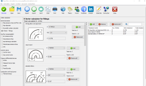
The calculator expects you to enter the size of the coefficient of local resistance K - pipe bends, t pieces, reductions, valves, etc. if there are any.
Pipeline curve
After entering these values, the calculator will be able to determine the characteristic of the pipeline - a curved line that shows the dependence of the flow through the pipeline and the pressure drop (head). That curve is visible at the pump performance diagram.
The system curve depends on pipe geometry and flow conditions.
Use the
pipe flow calculator
to calculate flow velocity and hydraulic parameters for the selected pipe.
Fluid properties
The calculator requires data entry for fluid flowing through the pipeline.
Density and viscosity values (kinematic or dynamic) must be entered.
The calculator allows you to select fluids from a list.
A large number of fluids are available - both liquids and gases.
It should be noted that the calculator assumes incompressible fluid flow,
so it is applicable to gaseous fluids only at lower pressure drops and lower speeds.
Flow regime has a significant impact on hydraulic losses.
You can
determine the Reynolds number
to check whether the flow is laminar or turbulent.
Pump and pipe performance curves
After entering all the previous values (pump, pipeline, fluid),
the calculator can display curved lines that represent the characteristics of the pump and pipeline.
For the calculation, it is necessary to click on the button - calculate the operating point.
Head vs Flow Curve and Pump Operating Point
The intersection of the pump performance curve and the system curve defines
the pump operating point. This point determines the actual flow rate and head
at which the pump will operate in the piping system.