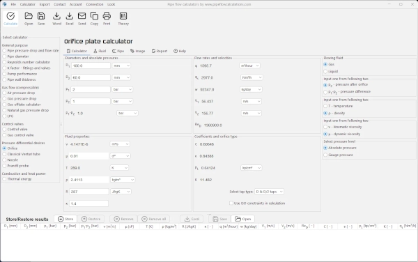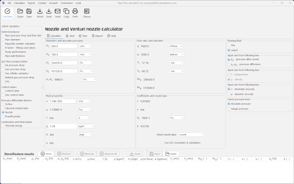
Thick-plate restriction orifice flow rate and bore diameter calculator
restriction orifice sizing for choked gas flow
Online Calculator
This calculator is not available as Online app.
Desktop App
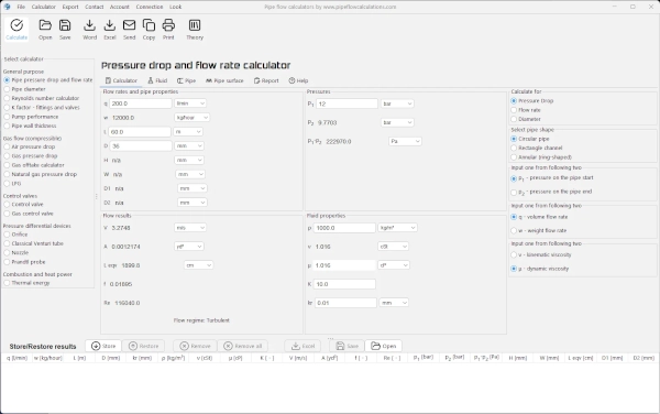
Desktop full-featured version.
Registration
Select a fair price and enable the full service:
- Switch between metric and imperial units in one click
- Export calculation results in Word .docx or Excel .xlsx format
- Preview results on one place and copy/paste it in your favorite text editor
- Send results back to your email
- Support the future of this project
And even more... get access to the full set of 19 desktop calculators available for Windows / macOS.
Full Year Service
Prepaid Monthly Cost
$2.50/month
Full year $29.95/year for new users and renewals before expiry
Why should you use this calculator?
Use this calculator to determine the choked gas flow rate through a thick square-edged restriction orifice or to calculate the required bore diameter for a specified gas flow rate.
A restriction orifice is normally used to limit gas flow or provide a controlled pressure reduction in a piping system. Unlike a standard thin orifice plate used for flow measurement, the thickness of a restriction orifice can significantly affect its flow characteristics.
What can the calculator determine?
The calculator supports two calculation scenarios:
Flow rate calculation - for a known pipe diameter D, bore diameter d and plate thickness t, the calculator determines the mass and volume flow rates through the restriction.
Bore diameter sizing - for a required mass or volume flow rate, the calculator determines the restriction-orifice bore diameter d.
In both cases, the calculator also verifies the critical-flow condition and the main applicability limits of the implemented Ward-Smith model.
When is this calculator relevant?
This calculator is intended for single-phase compressible gas flow through thick square-edged restriction orifices under critical or choked-flow conditions.
Typical applications include gas-flow restriction, pressure reduction, limitation of maximum gas flow and sizing or checking an existing thick restriction-orifice plate.
What data are required?
The main geometric inputs are the pipe internal diameter D, bore diameter d and plate thickness t. Operating data include upstream pressure p1, downstream pressure p2 and upstream gas temperature or density.
Gas properties include the specific heat ratio κ, specific gas constant R, dynamic or kinematic viscosity and compressibility factor Z. Bore surface roughness kr is used when evaluating friction inside the restriction bore.
How is the calculation performed?
The calculation is based on the Ward-Smith critical-flow model for compressible gas flow through thick square-edged orifices. The model accounts for the finite orifice-to-pipe area ratio and uses the critical-flow discharge coefficient Cd* together with the calculated critical pressure ratio.
The calculator also evaluates Reynolds number, bore friction and the thickness range associated with the Ward-Smith reattached-flow region. A low-area-ratio approximation is calculated internally as an additional consistency check.
What is critical or choked flow?
As downstream pressure decreases, gas velocity through the restriction increases until a critical condition is reached. The calculator determines the critical downstream pressure p* and the corresponding critical pressure ratio p*/p1.
For this calculation method, the required condition is: p2 ≤ p*. If the downstream pressure is above the critical pressure, choked flow has not been established and the calculator does not complete the calculation using this model.
Why is plate thickness important?
Gas separates from the sharp upstream edge as it enters the restriction bore. If the plate is sufficiently thick, the separated flow can reattach to the bore wall. The ratio t/d is therefore an important parameter for determining the applicable flow regime.
The implemented Ward-Smith plateau condition is: δ < t/d < ε, where the lower limit is δ = 0.3. The upper limit ε is not a fixed value; it is calculated from the bore-friction and Fanno-flow relationships for the current operating conditions.
What are the model limitations?
The calculator automatically checks the principal conditions used for application of the implemented Ward-Smith model:
Choked flow: p2 ≤ p*
Plate thickness: 0.3 < t/d < ε
Orifice-to-pipe area ratio: β = A2/A1 ≤ 0.1
Recommended Reynolds number: Re ≥ 10,000
In this calculator, β represents the area ratio A2/A1, not the diameter ratio d/D commonly represented by β in ISO 5167 orifice-meter calculations.
The choked-flow and plate-thickness conditions are required for the calculation. A larger area ratio or Reynolds number below 10,000 produces an applicability warning because the result may be outside the preferred range of the correlation.
The calculator also compares the full finite-area-ratio solution with the low-area-ratio approximation. A difference greater than 1% produces an engineering consistency warning. This check is an additional indicator and is not itself a Ward-Smith validity limit.
What results are calculated?
Depending on the selected calculation mode, the calculator determines the mass flow rate, upstream volume flow rate or required bore diameter. Additional results include pressure drop, critical pressure and pressure ratio, gas density, velocity, Reynolds number, Fanning friction factor, discharge coefficient and the relevant geometric ratios.
The calculation report also identifies whether the restriction is within the REATTACHED / WARD-SMITH PLATEAU REGION and displays the calculated limits used for this check.
Engineering use
This calculator is intended as an engineering calculation tool for evaluating thick square-edged restriction orifices. Users should verify that the selected geometry, gas properties and operating conditions are representative of the actual system and that the Ward-Smith model is appropriate for the particular application.
Desktop App
Fast. Accurate. Reliable.
Features in desktop app
- Save/Open multiple results
- Export to Word and Excel
- Print results
- Create list of custom fluid properties
- Resistance factor K for valves/fittings
- Pipe surface roughness selection
- Pipe material selection
- Gauge vs absolute pressure toggle
- Compressible isothermal flow
- Dry air isothermal flow
- Gas offtake flow
- Natural gas flow
- No admin rights required to install
Need a helping hand?
Powered by natural intelligence - NI

If you need a quick calculation, but you are not still familiar how to use the calculator, you can order calculation service from the calculator developer.